September 1, 2026
Vibe Fabrication: The Future of Hardware Prototyping
A field note on using an AI agent, interactive 3D review, parametric CAD, and printer-aware validation to shorten the path from an idea to a physical object.
By Kenny Trinh and Kira
What happens when describing, reviewing, and manufacturing a physical object becomes one continuous conversation?
I recently needed a small holder for a set of Mezastar Pokémon tags. Normally, even a simple object like this creates a surprisingly long chain of work: measure the objects, decide how they should sit, sketch the holder, model it in CAD, account for clearances and printer limits, export it, slice it, print it, and discover which assumptions were wrong.
I have written before about why talking to an agent preserves more of the context behind an idea. This experiment showed me the physical version. I started with a sentence: I need a holder for these tags.
The system asked how many it needed to hold, how I wanted to access them, whether they should stand upright or lie flat, what kind of retention mechanism I wanted, and which printer and material I planned to use. From there, it produced an interactive Three.js model that I could rotate and inspect before any manufacturing geometry existed.
I adjusted the design by looking at it and responding to what felt wrong. Then the system rebuilt the approved design parametrically in OpenSCAD, exported the STL, checked the mesh and fit relationships, and prepared it for printing.
The result was not perfect hardware generated from one prompt. It was something more useful: a much shorter loop between intent and a physical prototype.
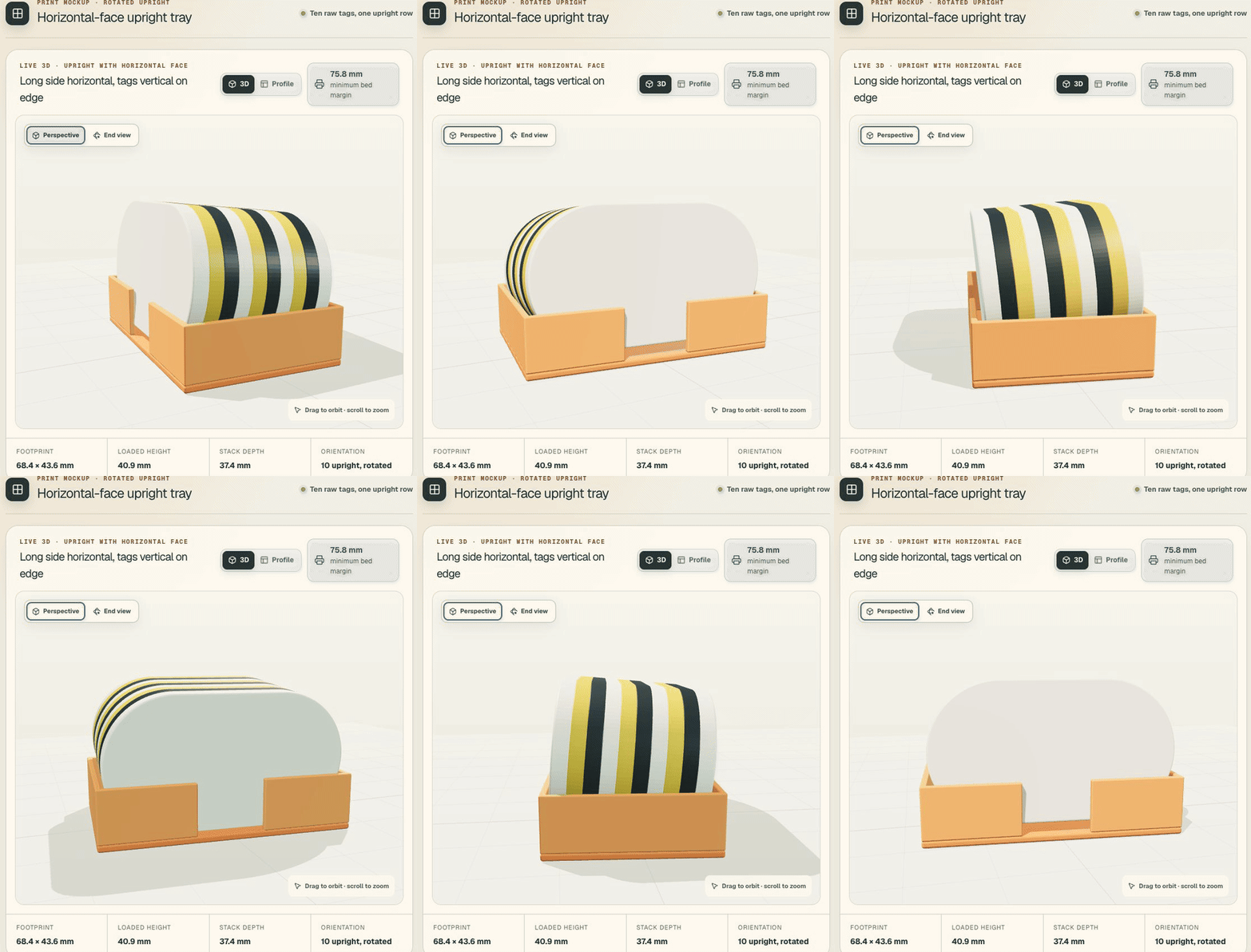
The interactive design review is a communication artifact. It is deliberately separate from the final manufacturing geometry.
The current hardware prototyping loop
Building a hardware product usually requires moving through several different representations of the same idea:
- Start with a need or an object you want to build.
- Measure the real objects and constraints around it.
- Explore the shape through paper sketches, foam, cardboard, clay, or an early physical mockup.
- Recreate the design in CAD.
- Add mechanisms, wall thicknesses, clearances, tolerances, and assembly details.
- Export and slice it for a specific printer, material, and orientation.
- Print or cut the parts.
- Hold the result, find the mistakes, and repeat.
Each step is reasonable. The friction comes from translating the same intent over and over.
A phrase like “easy to remove with one hand” has to become finger clearance, retaining-rail height, lean angle, and spacing. “Strong enough” has to become material choice, wall thickness, print orientation, and layer behavior. A sketch that looks right still has to become dimensions, constraints, and manufacturable geometry.
That translation work is where much of the time disappears.
A conversation instead of a chain of tools
The first version of my Vibe Fabricator breaks the workflow into three explicit stages.
1. Capture the printer, not just the idea
The process starts with the manufacturing environment: printer, usable build volume, nozzle, line width, material, layer height, support preference, and relevant calibration.
This matters because the same concept can require different geometry on different machines. A wall that is technically present in a model may not map cleanly to the printer’s line width. A nominal clearance may fuse on one setup and feel loose on another.
Unknown values remain visible assumptions. Manufacturer specifications and sourced dimensions can help, but they do not replace measuring the object in the condition in which it will actually be used. A bare tag and a tag inside a protective case are different objects.
2. Agree on the design before manufacturing it
Next, the system asks about the real use case: quantity, orientation, loading and removal, retention, assembly, moving interfaces, and aesthetics.
It turns those answers into a machine-readable specification and an interactive Three.js preview. The preview exposes parameters such as stack clearance, side clearance, rail height, wall thickness, floor thickness, finger access, footprint, and bed margin.
This makes iteration fast because I am not reviewing an abstract prompt or a static code file. I am reviewing the object as an object. I can rotate it, inspect its profile, see how the tags sit, and correct the design while the geometry is still cheap to change.
The preview is not converted directly into the final STL. It is a design-agreement artifact. That separation is important.
3. Rebuild the approved intent as manufacturing geometry
Only after approval does the system generate parametric OpenSCAD, export the printable parts, and validate the resulting meshes.
The checks include basics such as watertightness, winding, positive volume, bounding boxes, and connected bodies. They also include relationships that matter to the design: captured-object clearance, mating gaps, collisions, movement, and build-volume fit.
The computer can verify those digital relationships. The physical print still has the final word.
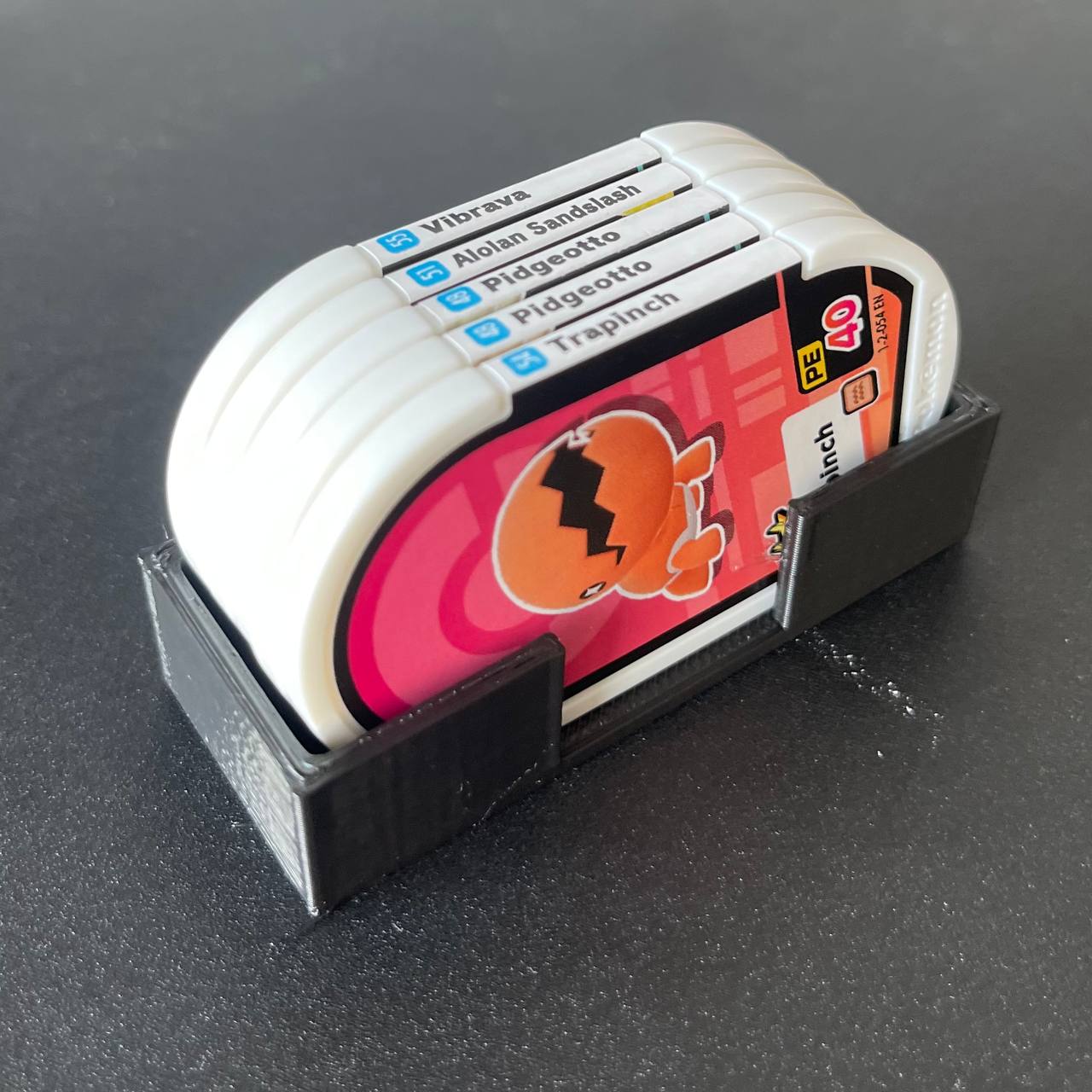
The first printed result. Physical fit and feel remain the authority, but the route from idea to this test was much shorter.
Vibe fabrication
The term I keep coming back to is vibe fabrication.
Vibe fabrication is creating physical objects by describing the intent, reviewing generated designs, and iterating through conversation while an agent handles measurements, machine constraints, parametric modeling, and manufacturing files.
The phrase borrows some energy from vibe coding, but it points clearly at the physical world. It can include 3D printing today and eventually CNC machining, laser cutting, electronics, and robotic assembly.
It is also narrower and more honest than “vibe manufacturing.” Manufacturing implies materials, loads, safety, repeatability, supply chains, and production processes far beyond generating a printable file. Fabrication describes what this experiment actually does: turns an idea into a physical artifact through a shorter, more conversational loop.
The important shift is not that the computer guesses everything from a sentence. It is that the conversation, design specification, visual review, manufacturing source, and validation report become connected parts of one loop. Instead of repeatedly translating the same idea between tools, I keep refining the intent while the system maintains the artifacts underneath it.
The software analogy, with physical consequences
Software development has already moved in this direction. We increasingly describe behavior, inspect generated artifacts, run tests, and iterate. The mundane parts do not disappear all at once. They become encoded into tools, reusable constraints, tests, and automated checks.
Hardware can follow a similar path, but it cannot pretend the physical world is just another renderer.
A model can be watertight and still print badly. A hinge can move in simulation and still bind because of material shrinkage. A holder can match the nominal dimensions and still feel unpleasant in the hand. Printer calibration, tolerances, material behavior, wear, and safety remain real.
The future is therefore not “prompt in, perfect product out.” It is a tighter partnership:
- The human owns intent, taste, tradeoffs, and physical judgment.
- The agent carries constraints across tools and keeps the artifacts synchronized.
- Deterministic software checks geometry and known relationships.
- The physical prototype closes the loop with reality.
That is already enough to remove a large amount of boring work.
The Iron Man workshop is becoming a useful reference
This experiment also reminded me of Iron Man, one of my favorite movies. Tony Stark’s workshop combines two ideas that used to feel inseparable from science fiction.
The first is JARVIS: a personal assistant that understands the project, keeps context, operates tools, and helps turn an incomplete thought into action. We are not at the fictional version, but current personal agents already feel perhaps 60 to 70 percent of the way toward the useful part of that idea. They can hold context, ask questions, research, write code, coordinate tools, and keep a project moving.
The second is the fabrication workshop: the holographic design surface, machines, and robotic systems that can create, modify, assemble, and repair physical things.
The interesting part is not whether we can reproduce Tony Stark’s technology exactly. It is that the interface between these two systems is becoming plausible.
In my current workflow, I describe an object, answer questions, inspect a generated design, approve it, and receive manufacturing files. The next extension is mostly a pipeline problem:
- Keep the design open as an interactive artifact while I make changes.
- Regenerate the parametric manufacturing model after each approved adjustment.
- Send the correct part files and machine settings to the printer.
- Monitor the print and preserve the exact version that was manufactured.
- Present assembly guidance, or eventually hand parts to an automated assembly system.
- Measure the physical result and feed those observations into the next revision.
That is still far from “create anything.” The printer cannot choose the right material, clear a failed print, insert hardware, test a latch by feel, or assemble arbitrary mechanisms without more equipment and feedback. But the shape of the loop is recognizable: talk, inspect, adjust, fabricate, test.
Tony Stark’s real advantage was not simply having a powerful printer. It was having one continuous environment where intent could move through design, simulation, fabrication, and testing without being manually reconstructed at every step.
That is the direction I find exciting.
What comes next
This first version is deliberately narrow. It focuses on FDM printing, parametric shapes, explicit approval gates, and inspectable handoffs. It works best when the design can be represented cleanly in OpenSCAD. Freeform surfaces, complex ergonomics, structural analysis, electronics, and production manufacturing require different tools and much stronger validation.
But the direction is visible.
A future hardware workflow may begin with a conversation, gather reliable dimensions from product data and direct measurement, understand the capabilities of the available machines, propose several mechanisms, generate an interactive prototype, and maintain the design as the user changes their mind. It may simulate fit and movement, prepare manufacturing files, and learn from the measurements of the printed result.
The biggest change is not faster CAD. It is reducing the distance between what I mean, what I can inspect, and what the machine can make.
My small tag holder is only a first experiment. But when an idea can move from a sentence, to a reviewable object, to validated manufacturing code, to something I can hold in my hand, hardware prototyping starts to feel less like operating a chain of tools and more like vibe fabrication: shaping an idea through conversation and then holding the result in my hand.